System Configuration
System Settings

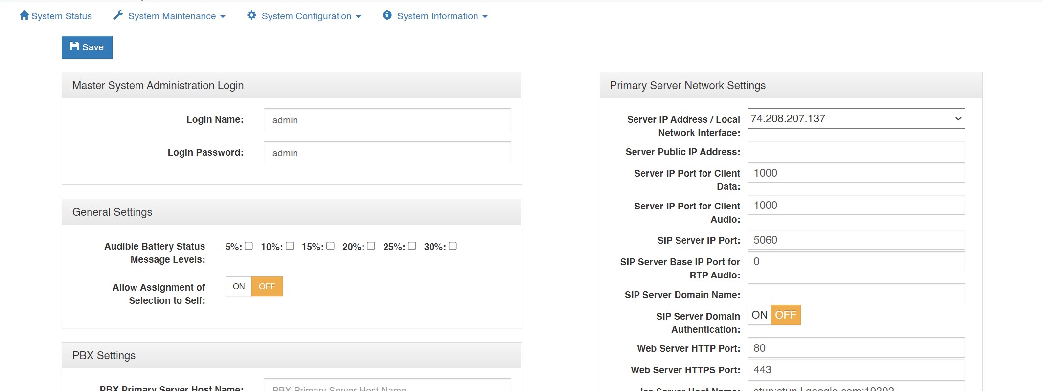
Master System Administrator Login : Displays and allows you to edit the master system administrator login name and login password.
Audio Settings
Audio Mix Sample Rate: Controls the maximum sampling rate supported by
the Virtual Matrix and thereby dictates the maximum fidelity for all Client
connections. There are 3 possible settings: Narrowband (8 KHz), Wideband (16
KHz), and Ultra-Wideband (32 KHz), which is the default setting. Narrowband is
approximately the same fidelity as a phone connection while Wideband more
closely approximates the fidelity of a professional analog, hardware-based
Intercom system. Clients by default will be set to the System's Audio sampling
rate. However, the client audio sampling rate can be specified at a lower rate but
never at a higher rate. Higher audio sampling rates have more significant
requirements both in computational speed and network bandwidth so careful
consideration must be made when choosing this setting with respect to server
hardware and network infrastructure.
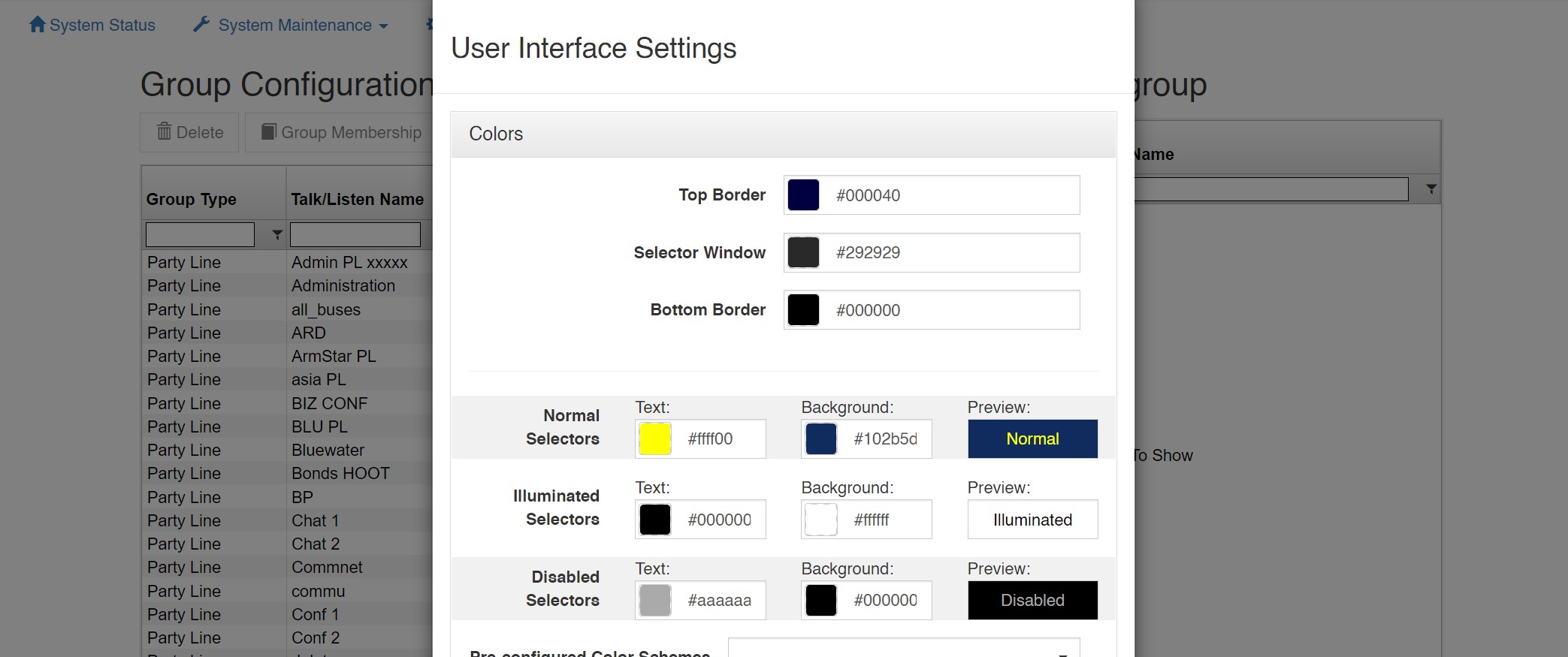
Voice Activity Indication Voice Activity Indication Color: Changes the text color and background color used to indicate voice activity on a given selector. The system interchanges its base colors (yellow text / navy background) with the selected activity indication colors (variable). For typical applications, the default color provides a subtle but noticeable indicator. For some applications, such as maintenance panels for hoot and holler systems, a more pronounced indicator (black text / white background) is generally required.
Audio Output Level Gain (Post-Mix): Adjusts the output level from the VCOM Virtual Matrix to the Control Panels and Device Interfaces in 6dB intervals 3 times to a maximum of 18dB. This is a global change throughout the system.
Primary Server Network Settings
Server IP Address / Local Network Interface: The IP address of the server hosting the
Virtual Matrix.
Server Public IP Address: The public IP address that is used to route data to the Server’s IP address within the LAN. This is only used when Network Address Translation (NAT) is being used on your LAN.
Server IP Port for VCOM Client Data: The TCP/IP port (default: port 1000) that all client side Control Panels and Device Interfaces use to transport data to the Virtual Matrix. The system has no restriction other than reserved ports. If the Virtual Matrix is behind a firewall and external access is required, a Port Forwarding entry must be added to route all traffic on this port to the internal Virtual Matrix IP address.
Server IP Port for Client Audio: The UDP port (default: port 1000) that all client-side Control Panels and Device Interfaces use to transport audio to the Virtual Matrix. The system has no restriction other than reserved ports. If the Virtual Matrix is behind a firewall and external access is required, a Port Forwarding entry must be added to route all traffic on this port to the internal Virtual Matrix IP address.
SIP Server IP Port: The IP Port (default: port 5060) for the integrated SIP Server. In general this value will never be changed as this is an industry standard port number. However, the value must be changed if multiple VCOM Virtual Matrix instances are to be run on the same physical computer.
SIP Server Base IP Port: By default, when set to zero all SIP RTP (Real-time [Audio] Protocol) sessions will establish the IP port number randomly in the range of 10000-42767. In many situations this is perfectly adequate. However, if the audio must transverse a firewall, it is not practical or safe to open such a large range of addresses. As such, by specifying an RTP Audio Base port the system will assign IP ports sequentially upward from the base port. Once an IP Port is assigned to a SIP client, it will never change unless the Base Port is itself changed.
SIP Server Domain Name The optional SIP Domain for the integrated SIP Server. If the SIP Domain is specified, it can be used as the SIP Proxy Name and the Registrar Name when configuring SIP clients. Regardless of whether the SIP Domain is specified, the Virtual Matrix IP Address can always be used as the Proxy Name and the Registrar Name.
Secondary (Failover) Server Network Settings
If you wish to set up a failover server for a second Virtual Matrix, and have purchased
‘Redundancy’, enter the relevant values. In an instance of a hardware or connectivity
failure client applications will reconnect to the failover server. Refer to Section 6 of the
VCOM Virtual Matrix User Guide for a detailed description of the failover capability.
Server IP Address: The IP address of the server hosting the Virtual Matrix.
Server NAT IP Address: The public IP address that is used to route data to the Server’s IP address within the LAN. This is only used when Network Address Translation (NAT) is being used on your LAN.
Server IP Port for VCOM Client Data / Audio: The Server IP Port for Client Audio under ‘Server IP Port for VCOM Client Data / Audio’.
Server IP Port for Failover Data The port that is used for the two Virtual Matrix servers to communicate with each other.
Failover Settings (visible only if the server is licensed for this feature)
Failover Activation Delay: Set the amount of time to delay the failover from coming online in place of the Primary Server.
Automatic Failback: Define when to restore the Primary Server. Choose the setting that best fits your procedures.
Media Server Settings (visible only if the server is licensed for this feature)
IP Port for Video Application Server WSS: The port that VCOM will use to establish a secure websocket with the Video Application Server.
Hostname for Video Media Server: The hostname of the system running the Video Media Server.
IP Port for Video Media Server WS: The port that VCOM will use to establish an unsecure websocket with the Media Server.
IP Port for Video Media Server WSS: The port that VCOM will use to establish a secure websocket with the Media Server.
Group Configuration

The ‘Group Configuration’ tab found in the ‘System Configuration’ area is used to add/edit/delete Party Lines and Fixed Groups, change selector names, and change group membership.
The main ‘Group Configuration’ window displays configured Party Lines and Fixed Groups.
To edit a Party Line or Fixed Group, highlight the one desired and click ‘Edit’ to bring up the ‘Group Configuration Add/Edit’ window.
To delete a Party Line or Fixed Group, highlight the one desired and click ‘Delete.’
To add members to a Fixed Group, click ‘Selected Group’ in the lower portion of the ‘Group Configuration’ window. Highlight a non-group member from the list of users and devices in the column on the left and click ‘Insert’ to add as a group member. To remove a group member highlight the user or device from the column on the right and click ‘Remove.’ Click ‘Clear’ to clear all group members.
To add a Party Line or Fixed Group, click the ‘Add’ button.
Type: Choose from the drop down box ‘Party Line’ or ‘Fixed Group’
Description: You may add a short description for the Party Line or Fixed Group or leave it blank.
Selector Talk Label: Add a name of up to 10 alphanumerical characters which will appear on the selector.
Latch Disable: Select latch disable to have the selector work as a momentary key.
User Interface Settings

This allows customizations of the VCP GUI such as the Colors (Background and Text), Selector Spacing, and 24-bit PNG graphic files that can be uploaded such as a logo.
Control Rooms
Introduction
The Control Rooms feature provides the ability to configure individual SIP tally pages. More information is available in the Control Rooms documentation.